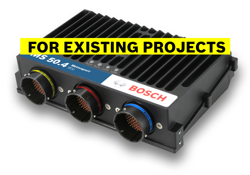
The VCU MS 50.4 is a highly powerful processing / logging unit for race applications.
Based on our broad base of platform function, we support you with customized VCU functions for a tailor-made solution.
In addition, you can quickly develop your individual customer software based on MATLAB/Simulink to significantly speed up algorithm development (automatic code and documentation generation, requires CCA package) – including extensive simulation capabilities.
- Downloads
- Features
- Application
- Technical Specifications
- Communication
- Installation Notes
- Ordering Information
- Dimensions
- Upgrades
- Legal Restrictions
Downloads
Features
- 667 MHz Dual Core Processor exclusively for vehicle control functionality (MATLAB based)
- Identical, dedicated 667 MHz Dual Core Processor exclusively for logging purposes
- High Speed Logging 200 kHz of 6 analog inputs (optional)
- Event logging, Configurable pre-event logging
Application
Processor for customer code | 667 MHz Dual Core |
Processor for logger | 667 MHz Dual Core |
Configurable math channels | |
User configurable CAN in/out messages | |
Online data compression | |
Internal logger
| |
Logging rates
| |
LTE Ethernet telemetry support | |
RS232 interface for GPS |
|
Technical Specifications
Mechanical Data
Size | 166 x 121 x 41 mm |
Weight | ≤ 660 g |
Protection classification | IP67 |
3 motorsport connectors, 198 pins in total | |
Max. vibration | Vibration profile 1 |
Operating temperature internal | -20 to 80°C |
Electrical Data
Supply voltage | 5 to 18 V |
Inputs
20 Analog channels 0 to 5 V, 0.5 % precision between 0.2 and 4.8 V, switchable pull-up |
8 Digital PWM inputs f_max=30 kHz Hall-type speed measurement possible, |
4 Digital PWM inputs f_max=30 kHz Hall- and DF11 type speed measurement possible, |
4 x universal Thermocouple |
1 x Bosch Laptrigger |
1 x TimeSync master and slave (specific to Bosch measurement system) |
Internal measurements: 1 x ambient pressure |
Outputs
2* x 7.5 A each, PWM High side, 50 Hz |
4* x 2.2 A each, PWM Low side, 10 kHz |
*can be enhanced by Upgrade I/O Package |
Sensor Supplies and Screens
5* x 12 V, 400 mA each |
5* x Switchable 5 V/12 V, 400 mA each |
4 A max overall current on all 12 V |
12 V ± 1 % precision on the pin |
20 x Sensor ground |
*can be enhanced by Upgrade I/O Package |
Adaptation and Documentation
Function documentation | Automatically created during code generation |
MatLab code generation | Support for customer own MatLab function development |
Software Tools (free download)
Data Analysis tool WinDarab 7 |
|
System Configuration tool RaceCon | Logger configuration, calibration, and online measurement |
Connectors
Connector LIFE (red) AS018-35PN | Mating connector AS618-35SN (not included) |
Connector SENS-A (yellow) AS018-35PA | Mating connector AS618-35SA (not included) |
Connector SENS-B (blue) AS018-35PB | Mating connector AS618-35SB (not included) |
Communication
Installation Notes
Maintenance Interval: 220 h or a maximum of two years |
Please remember that the mating connectors and the programming interface MSA-Box II are not included and must be ordered separately. |
Ordering Information
Vehicle Control Unit MS 50.4
Order number: F02U.V02.965-02
Vehicle Control Unit MS 50.4 incl. CCA Hardware Upgrade
Order number: F02U.V03.012-01
Rugged USB flash drive
Order number: F02U.V03.534-01
Connector for USB flash drive on car loom side
Order number: F02U.002.996-01
Adapter cable to PC USB-Port
Order number: F02U.V01.343-01
Breakout Box BOB 66-pole
Connector code: blue
Order number: F02U.V02.295-01
Breakout Box BOB 66-pole
Connector code: yellow
Order number: F02U.V02.298-01
Breakout Box BOB MS 7
Connector code: red
Order number: F02U.V02.293-01
Software Options
CCA Hardware Upgrade per device
Order number: F02U.V02.137-01
Multi CCA Hardware Upgrade VCU per device
Order number: F02U.V03.222-01
I/0 Package
Order number: F02U.V02.777-01
High Speed Logging Package
Order number: F02U.V02.779-01
CCP/XCP_MASTER
Order number: F02U.V02.213-01
Accessories
Opening tool for shellsize 18
Order number: F02U.V01.394-01
Dimensions


Upgrades
CCA Hardware Upgrade per device
Provides the option to run customer developed software code on Bosch device |
Multi CCA Hardware Upgrade per device
Enables the use of an extra core to utilize more computing power in the device |
I/O Package
Communication |
|
4 CAN | |
Inputs |
|
4 Analog channels | |
4 Digital PWM inputs | |
4 LVDT, 5 pin configuration, | |
Outputs |
|
4 “TTL” Digital output, 10 kHz, PWM, 25 mA each | |
2 PWM High side; 7.5 A each, PWM, 50 Hz | |
4 PWM Low side; 2.2 A each, PWM, 10 kHz | |
Power Supplies |
|
5 x12 V, 400 mA each | |
5 switchable 5 V/12 V, 400 mA each | |
** The tooth count differential between any two of the PWM inputs is available to measure e.g., shaft torsion. | |
High Speed Logging Package
6 ANA | 0 to 5 V, 200 kHz logging rate |
CCP/XCP_MASTER
Enables CCP/XCP master functionality to request data from foreign devices via CAN/CCP protocol, XCP over Ethernet (UDP) or XCP via CAN. |
Legal Restrictions
Generally blocked are direct and indirect business involving high risk destinations, including Russia, Belarus, Cuba, Iran, North Korea, Syria, Libya, Afghanistan, and certain non-governmental controlled Ukrainian regions. This list may change as geopolitics evolve.