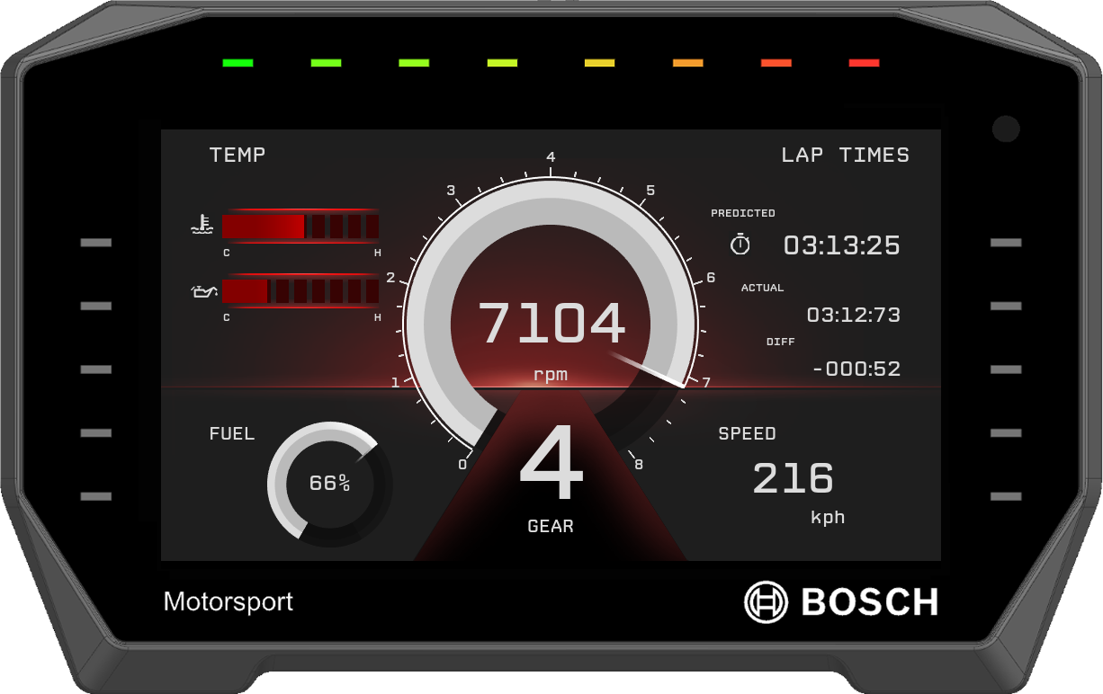
The display DDU 11 integrates a programmable full colour dashboard display with a data logging system for motorsport applications. Additional input devices can be connected via Ethernet, CAN buses, and RS 232.
A basic logging function of 100 channels with recording rate of 20 Hz (50 ms) (4 GB) is always included. The logger can be upgraded to full logging performance (max. 1 kHz (1 ms)). In addition, a 2nd logging partition of 4 GB can be activated. An optional external GPS Sensor keeps track of position on the racetrack.
With the DDU 11, a library of graphical elements for the individual design of display pages and a state-of-the-art user interface menu is available. For quick data transfer from the car, e.g., during pit stop, data logging to a USB stick is available as an option.
- Downloads
- Features
- Application
- Technical Specifications
- Communication
- Installation Notes
- Ordering Information
- Dimensions
- Upgrades
- Legal Restrictions
Downloads
Features
- Features user interface menu
- Features display element design generator
- 8 top-LEDs and 5 side-LEDs on both sides
- Supports GPS laptrigger, pre-dated lap time etc.
- Page change based on events possible
Application
Display 6.5” graphic color display 48 user configurable pages (12 pages organized in 4 switchable page sets) | |
Resolution | 800 x 480 pixel |
Supported image file formats | PNG, BMP, JPG, GIF |
Processor | 667 MHz Dual Core |
AD-Converters | 10 kHz sampling rate with digital downsampling filter |
Real time clock supply | Ultracap™, sustains realtime for 2 weeks |
Configurable math channels |
|
User configurable CAN in/out messages | Up to 256 IDs (128 in and out) |
Sampling rate | 20 Hz (50 ms) standard, |
Online data compression |
|
Internal logger
| |
Logging rates
| |
Ambient light sensor |
|
Technical Specifications
Mechanical Data
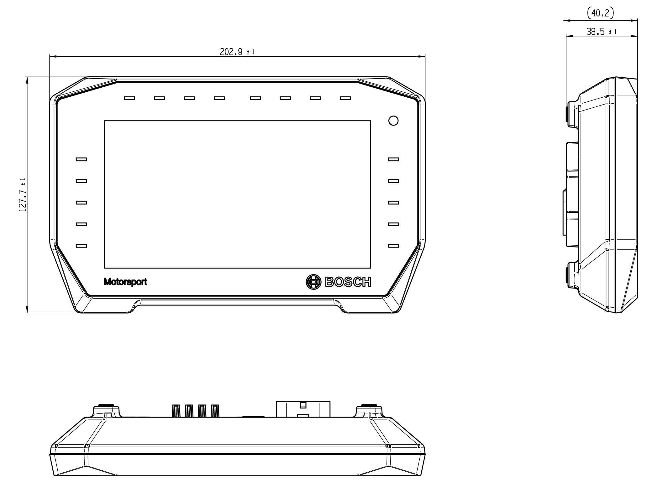
Size | 203 x 128 x 38.5 mm |
Weight | 649 g |
Protection classification | IP67 |
Operating temperature internal | -20 to 85°C |
Max. vibration | Vibration profile 1 (see Downloads or bosch-motorsport.com) |
Electrical Data
Supply voltage | 6 to 18 V |
Current consumption (w/o sensor supply) | <2 A (at 12 V) |
Inputs (option)
4 x analog In (5 V/12 bit), Digital In, Wheelspeed HALL, or Wheelspeed DF11 |
1 x analog In (5 V/12 bit), Digital In or Laptrigger In |
Switchable 3.01 kOhm pull-up resistors for all analog inputs |
Sensor Supplies and Screens
1 x Sensor supply 5 V +/- 1 % or UBAT switched (max. 250 mA) |
1 x Sensor ground |
Connectors and Wires
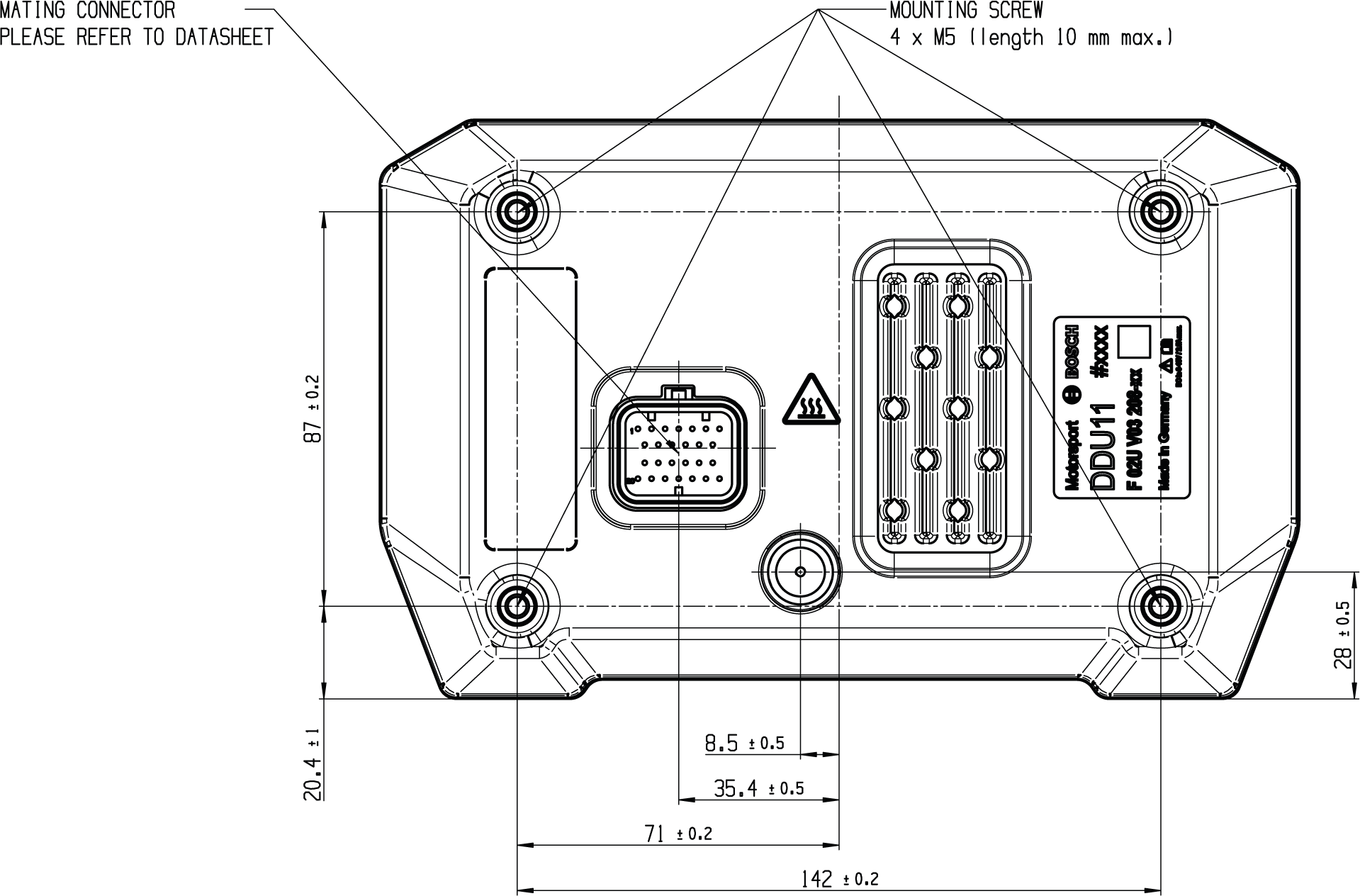
Mating Connector: TE Connectivity 3-1437290-7 |
Connector Pins: TE Connectivity 3-1447221-4 |
Pin Configuration
Pin | Name | Status |
1 | KL30_KL15/UBAT | Incl. |
2 | SENSGND | Incl. |
3 | SENSPWR (5 V or UBAT switched) | Incl. |
4 | SIG2_IN (Analog In, Digital In, Wheelspeed HALL, Wheelspeed DF11, switchable Pull-Up 3.01 k) | Opt. 1* |
5 | SIG4_IN (Analog In, Digital In, Wheelspeed HALL, Wheelspeed DF11, switchable Pull-Up 3.01 k) | Opt. 1* |
6 | USB_GND | Opt. 2* |
7 | USB_PWR | Opt. 2* |
8 | KL31/GND | Incl. |
9 | SIG5_IN_LAPTRG (Analog In, Digital In, switchable Pull-Up 3.01 k) | Opt. 1* |
10 | SIG1_IN (Analog In, Digital In, Wheelspeed HALL, Wheelspeed DF11, switchable Pull-Up 3.01 k) | Opt. 1* |
11 | SIG3_IN (Analog In, Digital In, Wheelspeed HALL, Wheelspeed DF11, switchable Pull-Up 3.01 k) | Opt. 1* |
12 | USB_DN | Opt. 2* |
13 | USB_DP | Opt. 2* |
14 | CAN_2_H_RS232_TX (switchable CAN or RS232) | Opt. 1* |
15 | CAN_1_H | Incl. |
16 | ETH_CHANNEL0_TXN (Ethernet 100BaseTX) | Incl. |
17 | ETH_CHANNEL0_TXP | Incl. |
18 | ETH_CHANNEL0_RXN | Incl. |
19 | ETH_CHANNEL0_RXP | Incl. |
20 | TIMESTMP_INOUT (Timesync) | Incl. |
21 | CAN_2_L_RS232_RX (switchable CAN or RS232) | Opt. 1* |
22 | CAN_1_L | Incl. |
23 | ETH_CHANNEL1_TXN (Ethernet 100BaseTX) | Incl. |
24 | ETH_CHANNEL1_TXP | Incl. |
25 | ETH_CHANNEL1_RXN | Incl. |
26 | ETH_CHANNEL1_RXP | Incl. |
Opt. 1*: Requires Software Upgrade IO_EXTENS
Opt. 2*: Requires Software Upgrade DATA_USB
Communication
CAN interfaces | 1 |
2nd CAN interface or RS232 with IO_EXTENS | e.g., Telemetry or GPS |
Ethernet 100BaseTX | 2 |
Laptrigger input | 1 |
Configuration via RaceCon | Over Ethernet or MSA-Box II |
CCP-Master, data acquisition from ECU that support CAN Calibration Protocol (CCP_MASTER option) | |
XCP-Master, data acquisition from ECU that support eXtended Calibration Protocol over UDP or CAN (CCP_MASTER option) | |
Installation Notes
Inspection services recommended after 220 h or 2 years, no components to replace. |
This product may contain open source software. Information about license terms and other obligations is given in the manual. |
Ordering Information
Display DDU 11
Order number: F02U.V03.208-03
Rugged USB flash drive
Order number: F02U.V03.534-01
Connector for USB flash drive on car loom side
Order number: F02U.002.996-01
Adapter cable to PC USB-Port
Order number: F02U.V01.343-01
Software Options
CCP/XCP_MASTER
Order number: F02U.V02.213-01
FULL_LOG_1
Order number: F02U.V02.304-01
FULL_LOG_2
Order number: F02U.V02.305-01
IO_EXTENS
Order number: F02U.V02.205-01
DATA_USB
Order number: F02U.V03.476-01
Accessories
Mating Connector Kit AMP Superseal
Order number: F02U.B01.201-01
Dimensions


Upgrades
CCP/XCP_MASTER
Enables CCP/XCP master functionality to request data from foreign devices via CAN/CCP protocol, XCP over Ethernet (UDP) or XCP via CAN. |
FULL_LOG_1
1,500 channels/1 kHz sampling rate on Partition 1 |
FULL_LOG_2
4 GB memory on Partition 2 |
IO_EXTENS
4 x Analog In (5 V/12 bit), Digital In, Wheelspeed HALL or Wheelspeed DF11 1 x Analog In (5 V/12 bit), Digital In or Laptrigger In Switchable 3.01 kOhm pull-up resistors for all analog inputs 1 x CAN or RS232 (switchable via RaceCon) |
DATA_USB
Data copy to USB flash drive |
ABSDIAG
Upgrade Onboard Diagnostic Package ABS M5
|
External switch for page selection, 12 steps | B261.209.658-01 |
External switch for brightness adjustment or page selection, 6 steps | B261.209.659-01 |
Legal Restrictions
Generally blocked are direct and indirect business involving high risk destinations, including Russia, Belarus, Cuba, Iran, North Korea, Syria, Libya, Afghanistan, and certain non-governmental controlled Ukrainian regions. This list may change as geopolitics evolve.
